Steps to Replace JSS Anti-Backdrive Mechanism
Service Procedure SP-JSS-190516-001
Tools & Supplies Required for This Procedure:
- 5mm Allen Wrench
- 13mm Wrench
- Needle Nose Pliers
- 3mm punch
- Mallet or suitable tool to drive punch
- Small flat-blade screwdriver
Procedure Steps:
(Before starting, please read instructions all the way through to ensure complete understanding)
To ensure safety, disconnect all electrical power to the saw.
Ready the Saw for Servicing:
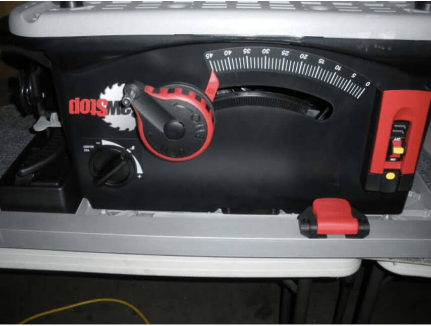
- Tilt the saw to 45 degrees.
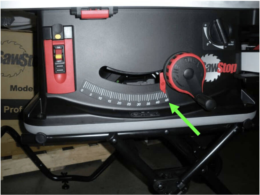
- Lower the blade completely and remove the fence from the saw and set aside.
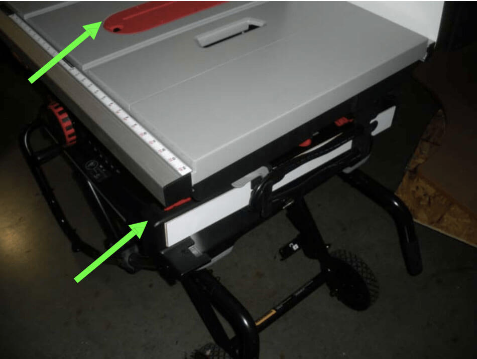
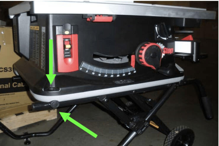
- Use a 5mm Allen wrench and a 13mm wrench to loosen and remove the four bolts that attach the saw to the cart and set aside.
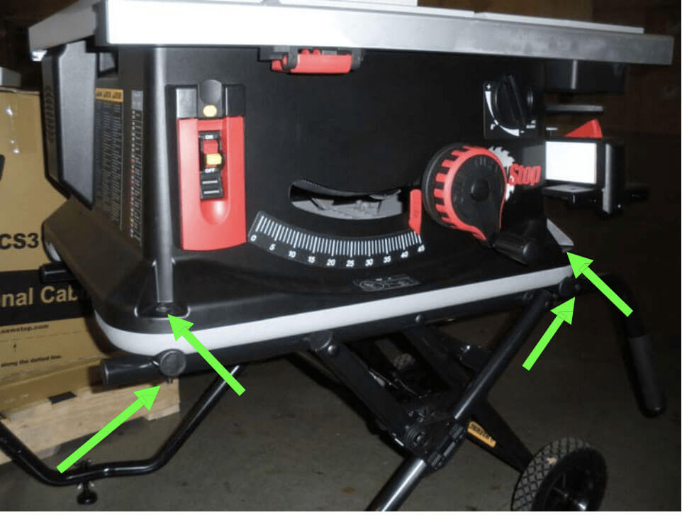
- Lift saw off of the cart and place upside down on a soft sturdy surface.
- There are 15 Phillips head screws around the outer edge of the bottom that attach it to the saw body. Starting with the screw to the left of the counter spring indentation at the back and working counter clockwise, remove all 15 and the bottom and set aside. NOTE: When the last screw is removed, the bottom will spring upward a bit.
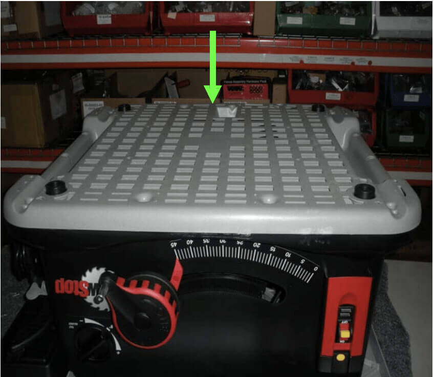
- Remove bottom cover and set aside.
Remove and Reinstall Anti-backdrive Unit:
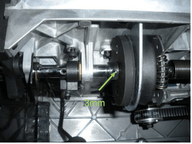
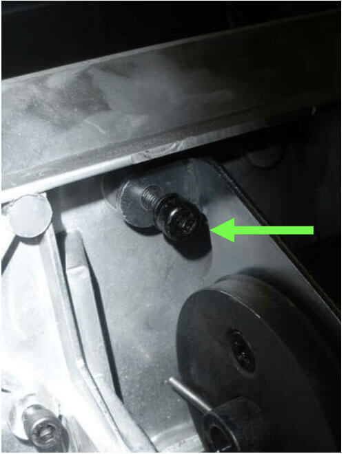
- Using handwheel, line up shaft so that 3mm pin can be driven out.
- Pop off left-hand e-ring (typically a small flat-blade screwdriver and a pair of needle-nosed pliers work best to accomplish this.)
- Using the 3mm Pin punch and a mallet, drive out the 3mm spring pin.
- Partially pull out the input shaft so that it clears the anti-backdrive unit.
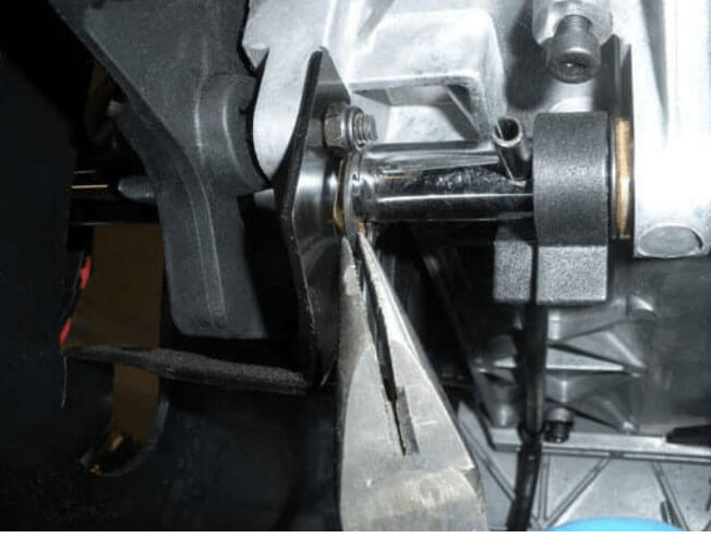
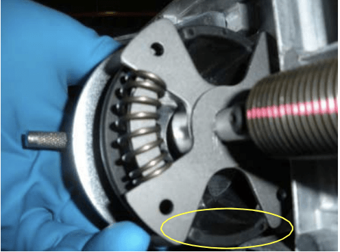
- On the anti-backdrive unit, unscrew the two 5mm cap screws…
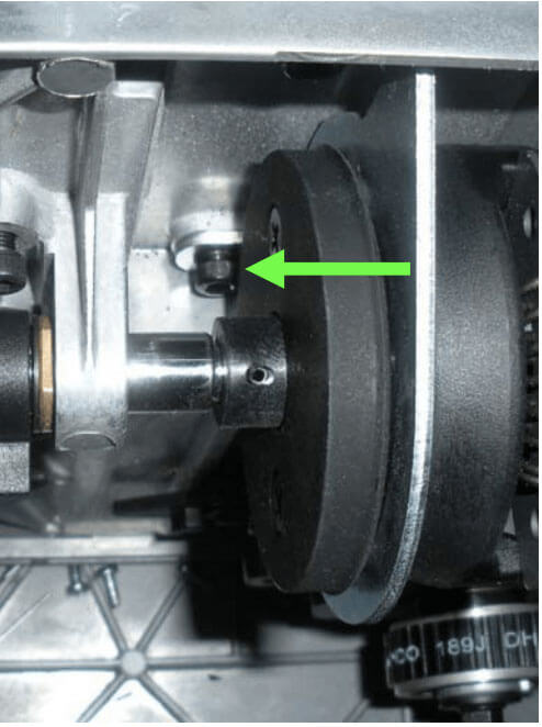
- then pull the mechanism out to the left (it looks like this.)
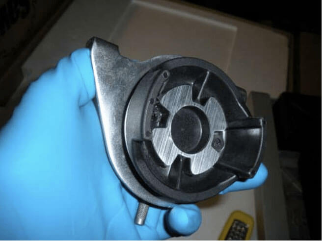
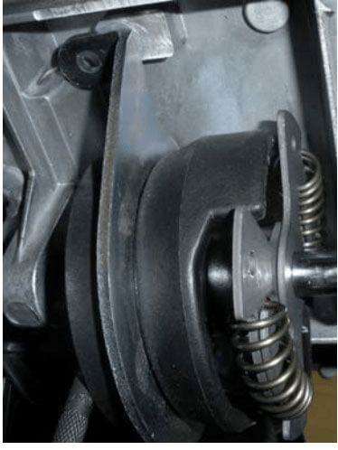
- Line up the replacement anti-backdrive unit and install. Note: you can use the 3mm pin punch to turn anti backdrive mechanism so that tabs line up better with scissors wings.
- Usually getting the lower tab in first, then the upper tab will work best.
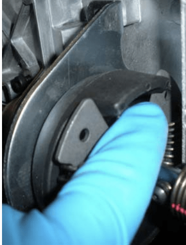
- You may have to deflect the scissors with your thumb to get the upper tab engaged.
- Once you have the replacement anti-backdrive unit engaged with the spring shaft, reinstall the 5mm socket head cap screws. Note: be careful not to cross-thread, the threads are aluminum, and you can ruin them and the whole elevation mechanism.
- Re-connect input shaft.
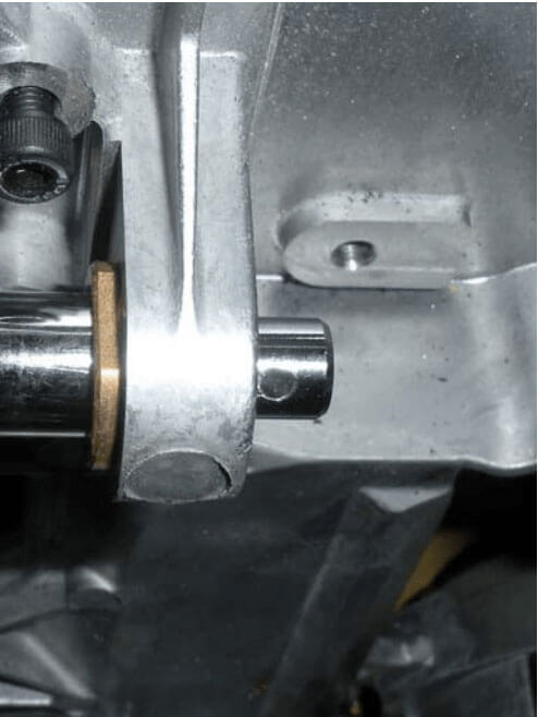
- Put the 3mm pin back in.
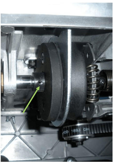
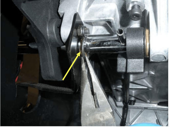
- Install left hand e-ring (yellow arrow) – you’re done with replacement.
Replace Bottom Cover and Reinstall saw on Stand:
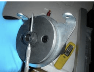
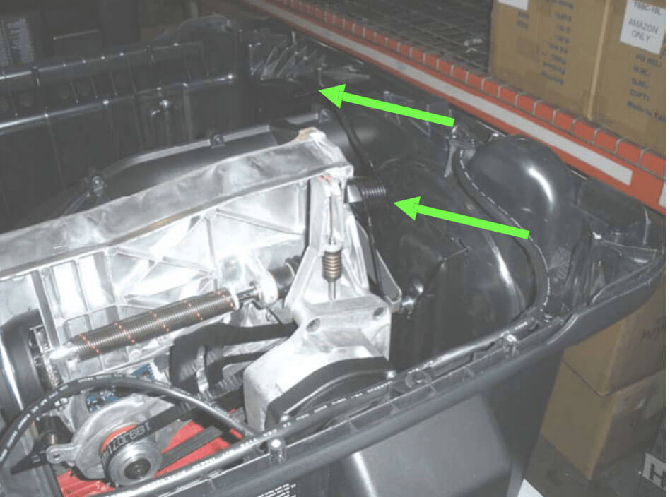
- Ensure the saw is tilted back to 90 degrees. Above the motor is the counter balance spring that must be in the up position leaning against the trunnion.
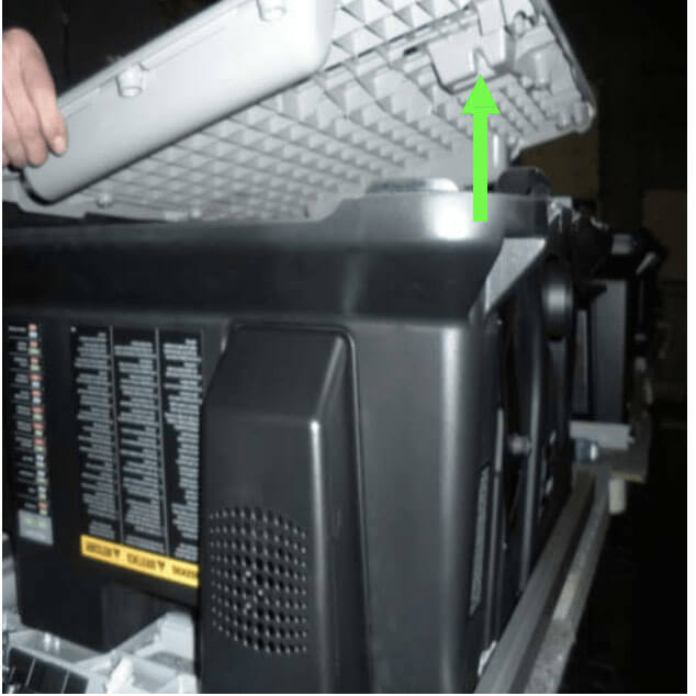
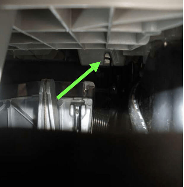
- There is a small groove on the bottom of the indentation that the top of the counter balance spring must seat in. You’ll want to “hover” the base over the saw and slowly lower it until the two match up.
- Reinstall the 15 screws starting with the one that is left of the indentation. NOTE: When using a power screw driver, the torque must be set about midrange or you WILL strip them.

- Place the saw back on the cart and reinstall the four 5mm bolts and nuts.
Questions?
Contact the SawStop Customer Support Center with any questions or suggestions:
Call: (503) 582-9934
Email: [email protected]