Installing the PCS175 208-240v Switch Box & Contractor Assembly
Service Procedure SP-PCS-190703-02
Tools & Supplies Required for This Procedure:
- 2 Phillips screwdriver
- 6mm Allen wrench
- Wire nut (suitable for connecting 2x 14ga stranded wires)
Procedure Steps:
(Before starting, please read instructions all the way through to ensure complete understanding)
- Disconnect all electrical power to the saw.
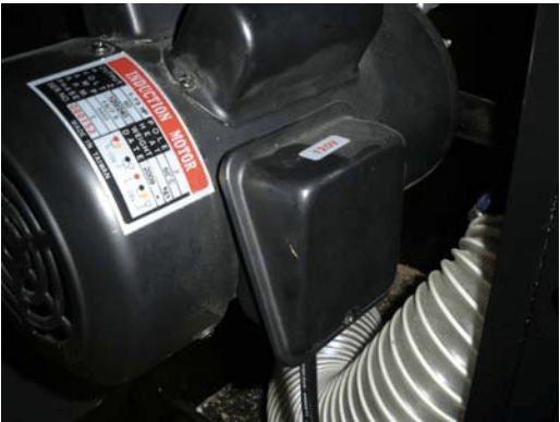
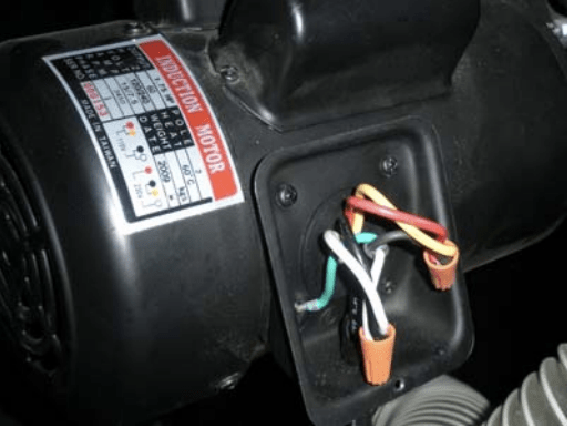
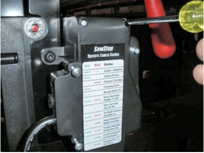
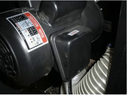
- Ensure the tilt is set to 0°, open the motor cover door, and remove the cover from the junction box on the motor. Note wires are shown connected for 115v operation (See Figure 1 & 2.)
- Remove the wire nuts and unscrew the ground lead.
- Loosen the strain relief coupling and slide the motor cable out from the junction box; pull the motor cable out through the grommeted hole in the side of the cabinet.
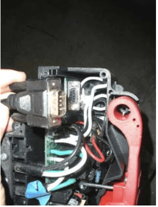
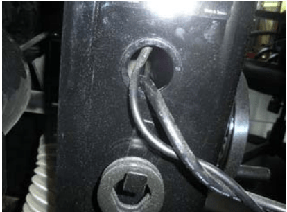
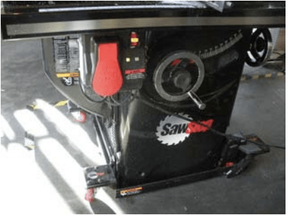
- Remove the left side cover to the switch box, and disconnect the cartridge cable (D-SUB connector). At this point all the cables leading to the switch box should be hanging free. (See Figure 3.)
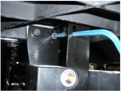
- Remove the switch box from the contractor bracket by removing the four 5mm button head socket screws that hold it to the bracket. Mount the switch box to the new 208-240v contractor bracket assembly.
- Loosen and remove the two bolts holding the switch box mounting bracket to the underside of the saw table.
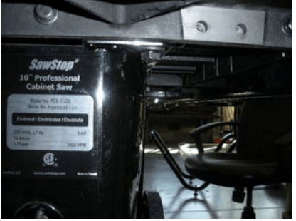
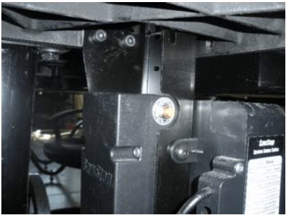
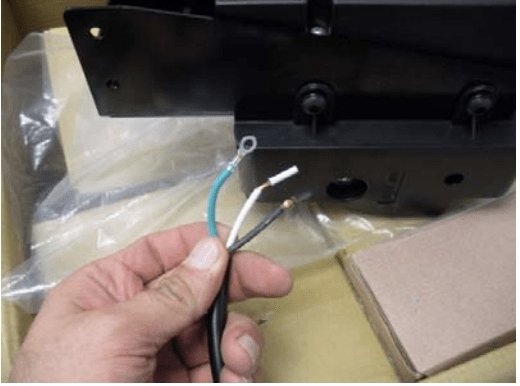
- Attach the new contractor/switch box assembly to the mounting holes on the underside of the table, using the same bolts that were used to mount the old switch box. (See Figures 4, 5 & 6.)
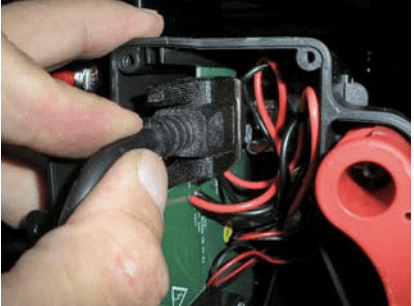
- Install the cartridge cable in the switch box. Plug the cable into the D-SUB connector, and gently tighten the hold-down screws. (See Figure 7.)
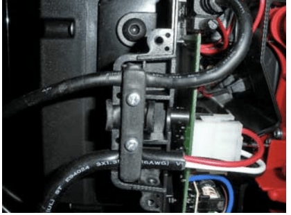
- Install the white Molex connector from the contractor assembly into the switch box. Make sure the cable is seated firmly into the switch box connector. Take care not to crush the cable when reinstalling the strain relief bar inside the switch box. (See Figure 8.)
- Replace the left side cover on the switch box. (See Figure 9.)
- Route the motor power cable through the grommeted hole into the cabinet, and run it into the motor junction box through the strain relief coupling. (See Figure 10.)
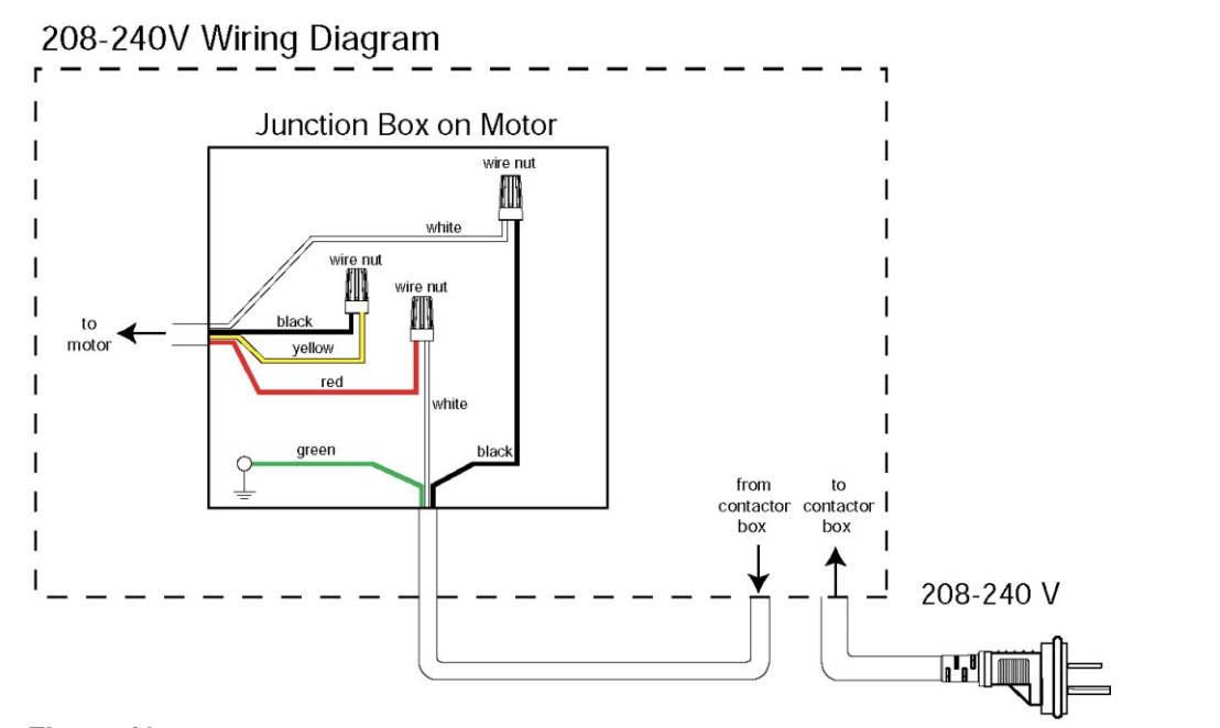
- Using wire nuts, connect the motor leads to the motor cable coming from the contractor assembly, and screw the ground lead down to make a solid connection. Position the cable so that the end of the outer insulation cover is even with the strain relief, and tighten the coupling so that the cable is firmly attached. Note the wiring is now configured for 208-240v operation (See Figures 11 & 12.)
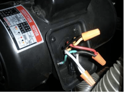
- Note the 208-240V wiring connection diagram for the 1.75HP motor (Figure 13 below.) Ensure you connect the leads correctly for 208-240V operation.
- Reinstall the motor junction box cover. If there is a gasket, take care that it is properly positioned so that sawdust will not get into the junction box once it’s closed up. (See Figures 14 & 15.)

- At this point the power cables should be fully installed. Note: it is permissible to change the plug from the design provided to match your local outlet or extension cord. Just be sure you hook up only two hot lines and a ground. No neutral line is required.
- Plug the power cord into a 208-240VAC outlet or extension cord. Turn on the toggle switch on the switch box and check for normal operation. The saw should operate just as before, coming to a solid green LED after initializing. (See Figure 16.)
Questions?
Contact the SawStop Customer Support Center with any questions or suggestions:
Call: (503) 582-9934
Email: [email protected]