Installing CNS175 230V Contactor Assembly
Service Procedure SP-CNS-190703-02
Tools & Supplies Required for This Procedure:
- #2 Phillips screwdriver
- 10mm combination wrench
- 8mm combination or socket wrench
- 5mm Allen wrench
- 4mm Allen wrench
- 3mm Allen wrench
- Cable tie (provided in repair parts kit)
- Wire nut (provided in repair parts kit)
- Electrical tape
Procedure Steps:
- Before starting, please read instructions all the way through to ensure complete understanding.
- Although described as a 230V unit, the 230V contactor assembly is actually rated for single phase power from 208VAC to 240VAC.
- Disconnect all electrical power to the saw.
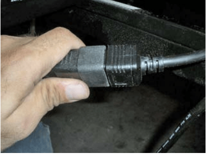
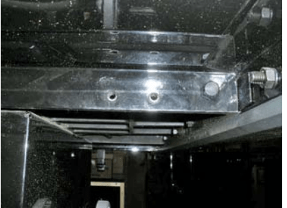
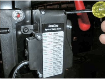
- Unplug the motor power cable connector. (See Figure 1.)
- Using the tilt handwheel, tilt the motor away from 90° to give some room to work.
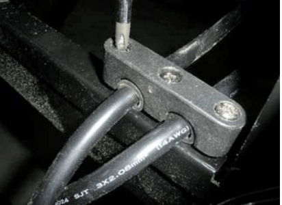
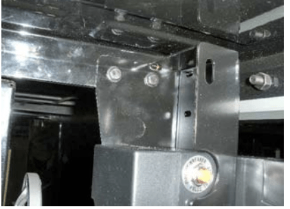
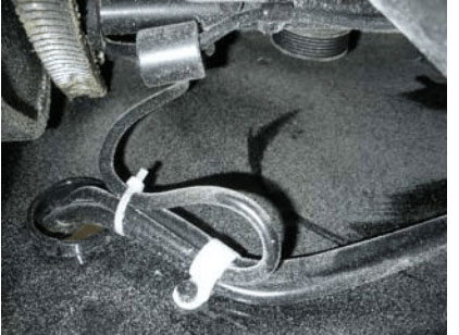
- Using a # 2 Phillips screwdriver, remove the three screws attaching the power cable strain relief clamp at the left rear of the saw. (Note the positions of the rubber grommets on the power cables for future reference.) Set the strain relief and screws aside. (See Figure 2.)
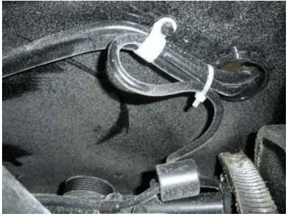
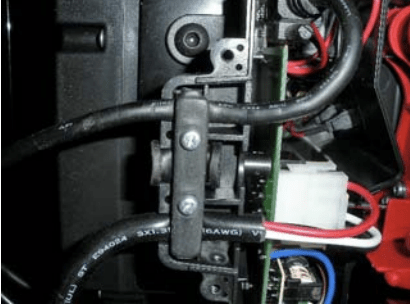
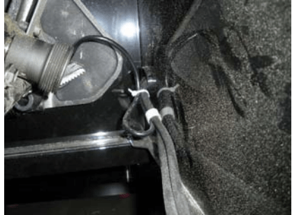
- On the inside left wall of the saw cabinet, dismount the cable clip holding the power cables to the inside of the saw. (See Figure 3.) Use a 4mm Allen wrench for the screw, and an 8mm socket or combination wrench for the cap nut on the outside of the cabinet. Set the clip and screws aside. There is a cable tie installed on the cartridge cable to take up extra slack and keep the cable from getting caught up in the tilt gearing. Clip the cable tie and discard it; there is a new cable tie supplied with the new switch box/contractor assembly.
- Pull the motor and power cables out through the grommeted hole on the left front corner of the saw. Leave the cartridge cable in place.
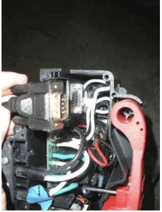
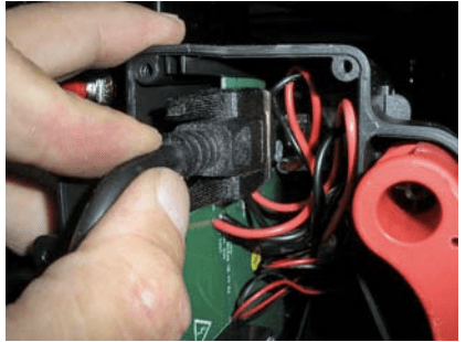
- Remove the left side cover to the switch box, and disconnect the cartridge cable (D-SUB connector). At this point all the cables leading to the switch box should be hanging free. (See Figure 4.)
- Using a 10mm combination wrench and 5mm Allen wrench, loosen and remove the two m6x20 bolts holding the switch box mounting bracket to the underside of the saw table, and remove the switch box from the 115V contractor bracket and lay it aside.
- Attach the new 230V contractor and bracket assembly to the mounting holes on the underside of the table, using the same M6x20 bolts that were used to mount the old switch box. (See Figures 5 & 6.)
- Mount the switch box from the old 115v contractor & bracket to the new 230V contactor and bracket. With the left side cover removed, install the cartridge cable in the switch box. Plug the cable into the D-SUB connector, and gently tighten the hold-down screws. (See Figure 7.)
- Plug the power cable into the white 4-pin power connector. Take care not to crush the cable when reinstalling the strain relief bar inside the switch box. (See Figure 8.)
- Replace the left side cover on the switch box. (See Figure 9.)
- Route the two power cables through the grommeted hole and out the back of the saw. Making sure the pre-installed rubber grommets on the cable are downstream from the cable clip, re-attach the cable clip holding the cables against the inside wall of the cabinet. Make sure there is adequate slack in the cartridge cable to allow for a full 45° tilt without straining the cable, but not too much slack, to avoid having the cable get caught up in the tilt gearing. Reinstall the cable tie removed in step 5 if needed. (See Figures 10 & 11.)
- Taking care to lay the pre-installed rubber grommets in the proper tracks, gently pull the slack out of the power cables and re-fasten the strain relief clamp.
- Follow these steps to rewire the motor for 220-240V operation:
- Remove the motor belt by opening the belt guard and lifting the motor upward to release tension in the belt.
- Remove the motor from the saw by loosening the two lock down set screws that hold the motor in place (use a 3mm hex key), and then slide the mounting pins out of the corresponding holes in the rear trunnion (see Fig. 17 on page 21 of the Contractor Saw Owner’s Manual).
- Locate the junction box underneath the motor (see Fig. 38 on page 33 of the Contractor Saw Owner’s Manual) and remove the cover by loosening the Phillips-head screw.
- Inside the junction box are wires connected by two wire nuts. One wire nut connects two black wires and one white wire. The other wire nut connects red, yellow and white wires. Remove any electrical tape from the two wire nuts and then remove the two wire nuts.
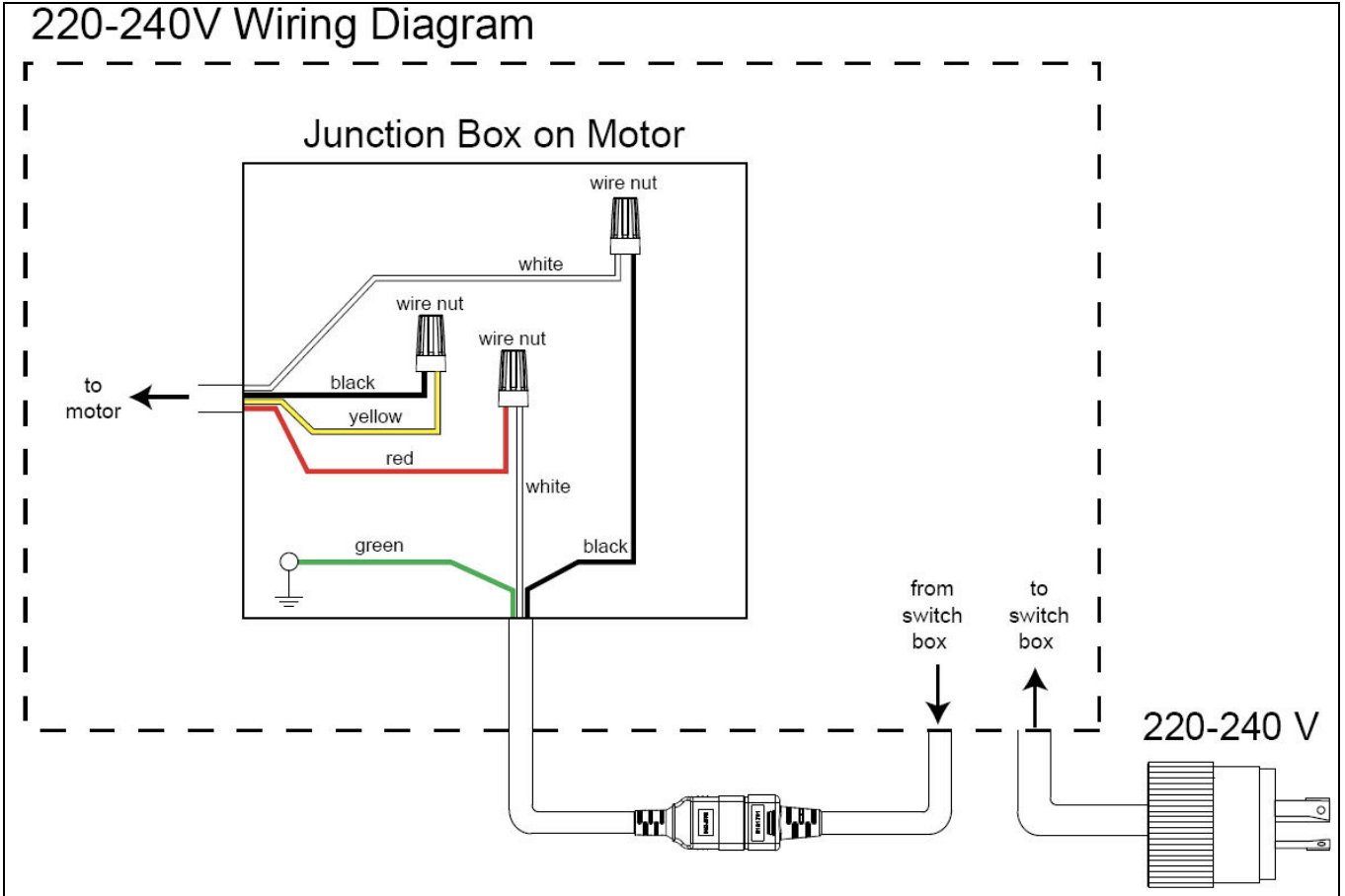
- Re-wire the leads as shown in the 220-240V wiring diagram in Figure 12 below.
- Connect the black wire coming from the power cord to the white wire coming from the motor. Connect the white wire coming from the power cord to the red wire coming from the motor. Finally, connect the black wire coming from the motor to the yellow wire coming from the motor.
- You will need a third wire nut to re-wire the saw for 220-240V power (provided with the new contractor.) Use the three wire nuts to connect the wires and then wrap each wire nut with two layers of new electrical tape.
- Double check the wiring to make sure it matches exactly the 220-240V schematic in Figure 12 above, and then re-attach the junction box cover.
- Reinstall the motor and motor belt as described on pages 21 and 22 of the Contractor Saw Owner’s Manual.
- Plug in the motor power plug. At this point the power cables should be fully installed.
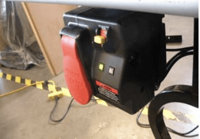
- Plug the power cord into a 220-240VAC outlet or extension cord. Turn on the toggle switch on the switch box and check for normal operation. The saw should operate just as before, coming to a solid green LED after initializing. (See Figure 13.)
Questions?
Contact the SawStop Customer Support Center with any questions or suggestions:
Call: (503) 582-9934
Email: [email protected]